
What Can Go Wrong, and How Turbomachinery Controls Can Address Those Challenges
Floating production storage and offloading units (FPSOs) are vessels that essentially act as mobile offshore oil and gas production and storage facilities. These vessels are equipped with processing equipment that is used for the separation, storage and offloading of oil and gas extracted from sub-sea reservoirs. The gas produced in FPSO is used for pipeline gas transportation, injection into the reservoir for enhanced oil recovery (EOR), gas-lift, and onboard gas turbine fuel.
[See also: Guide to FPSO (Floating Production Storage and Offloading)]
Figure 1 shows the simplified FPSO gas treatment processes of pre-salt FPSO installations. The separated gas is first compressed by main compressor A, then is treated inside the gas dehydration unit (GDU). Next, dehydrated gas is either sent to the CO2 removal process, or may be bypassed when all or part of the gas must be injected. After that, the separated CO2 is compressed in the CO2 compression train to increase its pressure to the minimum pressure level required for injection. Main compressor B is used to increase the gas pressure when needed for gas export, fuel gas, and/or off-spec gas injection. Combined compressors (also called injection compressors) are used to increase the pressure of off-spec gas or CO2 to the level required for the enhanced oil recovery (EOR) injection.
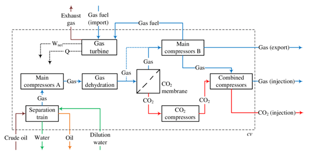
Figure 1 - Simplified scheme of the FPSO processes (Carranza Sánchez, Yamid & De Oliveira Junior, Silvio. (2015). Assessment of the exergy performance of a floating, production, storage and offloading (FPSO) unit: Influence of three operational modes)
Operating Modes and Energy Efficiency
Carranza Sánchez, Yamid and De Oliveira Junior, and Silvio, 20151 conducted an assessment of the exergy performance of an FPSO unit, which was influenced by the typical three operational modes of pre-salt FPSO installations. The evaluation/assessment of the exergy performance was carried out with a main goal of investigating the influence of the operating modes on FPSO exergy efficiency and CO2 emissions.
Although the research didn’t consider turbomachinery controls — such as the antisurge and loadsharing control systems of the compressors — and it assumed same mass flow, temperature, and pressure of crude oil, the research highlighted that it is relevant to consider that the mode operation depends on the crude oil composition. It also indicated the importance of considering the variations in the compression schemes and pressure levels as well.
By adding the complexity of changing crude oil’s properties (mass flow, temperature, and pressure) during the reservoir’s life cycle and in different operation modes, the control performance of the turbomachinery compression trains became the most critical factor to consider in reducing FPSO operational and energy efficiency challenges.
To better understand the compression schemes and pressure levels of the different pre-salt FPSO operating modes, and how turbomachinery controls play an important role in FPSO performance and energy efficiency, Figure 2 and Table 1 demonstrate typical compression train configurations and related turbomachinery control loops.
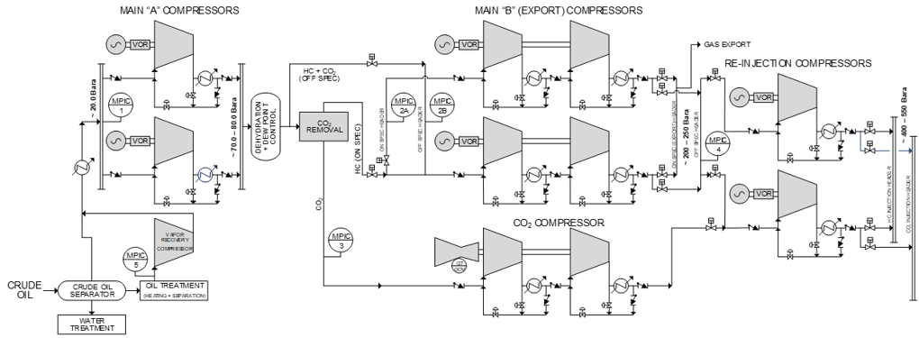
Figure 2 - Simplified scheme of the FPSO processes including compression trains control loops
|
CONTROL LOOP NAME IN FIGURE 2 |
DESCRIPTION |
CONFIGURATION NOTES |
|
MPIC-1 |
Main “A” Trains Suction Header Pressure Control
|
Two or three trains, and almost always operate in parallel |
|
MPIC-2A |
Main “B” Trains On-Spec Suction Header Pressure Control
|
Two or three trains operate in parallel for either on-spec or off-spec gas; OR One train handles on-spec gas and the other train handles off-spec gas. |
|
MPIC-2B |
Main “B” Trains Off-Spec Suction Header Pressure Control |
|
|
MPIC-3 |
CO2 Train(s) Suction Header Pressure Control |
One or two trains, which operate in Parallel in case of two trains. |
|
MPIC-4 |
Re-injection Trains Suction Header Pressure Control |
One train in operation, or both in parallel, or both in “stand-alone” operation. |
|
MPIC-5 |
Vapor Recovery Unit (VRU) Train Suction Pressure Control |
Usually one train only, but sometimes two trains in parallel. |
Table 1 - FPSO compression train control loops
We can summarize the variations in the compression schemes and pressure levels in the typical three pre-salt FPSO operational modes as:
Operation Mode 1
Operation mode 1 is used when the crude oil is saturated with water/CO2. Figure 3 demonstrates the operation scheme of that mode. The crude oil is treated, and the process’s recovered vapor is compressed and transferred to the main compressors along with the separated gas. After main compressor A raises the pressure to 79 bar and the dehydration unit reduces the moisture content, the gas bypasses the CO2 removal unit and moves directly to main compressor B. The gas is compressed to 250 bar in the main compressor B and finally to 494 bar in the combined compressors to be injected as off-spec gas.
As all the gas has been injected to the reservoir in that mode, the fuel gas is imported for the gas turbine's fuel needs.
The control loop MPIC-2B sets the performance of the main “B” trains, which usually operate in parallel, while MPIC-2A loop is “deactivated”. The control loop MPIC-4 sets the performance of the re-injection trains, which usually operate in parallel.
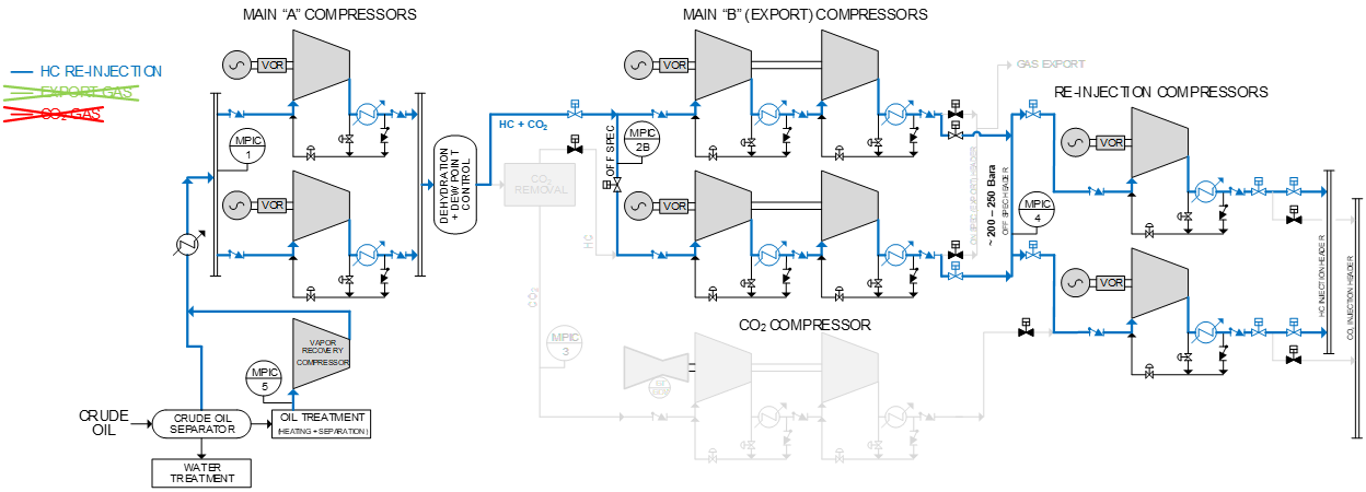
Figure 3 - Mode 1 simplified scheme of the FPSO processes including compression trains control loops
Operation Mode 2
Operation mode 2 is used when the crude oil has 50 percent basic sediment and water (BSW), which allows FPSO operators to export gas (on-spec gas).
In this mode, part of the gas is treated in the CO2 removal unit before exporting, while the remaining part is used for injection. Gas export is compressed to 250 bar, while the separated CO2 and remaining separated gas (off-spec gas) is compressed to 494 bar for injection.
Also in this mode, the fuel gas required for the gas turbines is provided as part of the exported gas.
As shown in Figure 4, one main “B” train handles on-spec gas for export, with MPIC-2A setting its performance in a “stand-alone mode,” while the other main “B” train handles off-spec gas for re-injection, with MPIC-2B setting its performance in a “stand-alone mode.”
The CO2 train provides primary compression for the removed CO2, with its performance set by MPIC-3.
Each re-injection train operates in its own “stand-alone mode,” with one train handling the off-spec gas and the other handling CO2 gas.
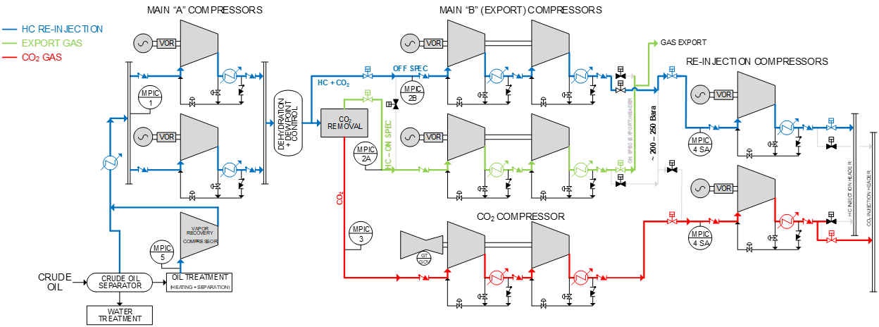
Figure 4 - Mode 2 simplified scheme of the FPSO processes including compression trains control loops
Operation Mode 3
Operation mode 3 is used when the crude oil has the maximum oil and gas contents. All the separated gas is exported as on-spec gas in that mode after dehydration and CO2 removal. The pressure conditions are similar to mode 1 and 2, and the fuel gas is provided from the exported gas as well.
As shown in Figure 5, the main “B” trains handle the on-spec gas for export. MPIC-2A control loop sets their performance in parallel and MPIC-2B loop is “de-activated.”
As the CO2 train provides primary compression for the removed CO2, the train performance is controlled by MPIC-3 control loop, and the CO2 gas is further compressed in one re-injection train with the other re-injection train stopped. MPIC-4 sets the performance of this single re-injection train in a “stand-alone mode.”
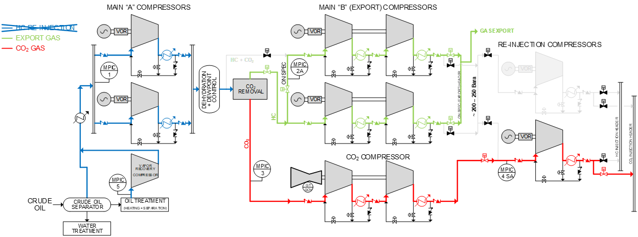
Figure 5 - Mode 3 simplified scheme of the FPSO processes including compression trains control loops
What Can Go Wrong, and How Turbomachinery Controls Can Address Those Challenges
- Since the gas’s molecular weight (MW) may vary, each of the re-injection trains could handle either off-spec gas (MW 21 ~ 35), CO2 (MW 40 ~ 42), or any intermediate mix, and each Main “B” train could handle either off-spec gas or on-spec gas as well. Accurate compressor antisurge control with proper invariant proximity-to-surge calculation is especially challenging. This means that the compressor surge control margin is never unnecessarily large to accommodate “shifts” in the surge limit line of the compressor as the gas composition varies, which directly enhances the energy efficiency of the compressor train.
- As compression trains can operate in stand-alone mode, handling different gasses with different dynamic characteristics requires different compressor performance/process controller tuning. Also, when the parallel compression trains operate in a parallel configuration, the performance/process controller must adapt smoothly to these different operating scenarios without operator intervention.
- The lack of integration in compressor antisurge and performance controls usually results in energy loss or unplanned shutdowns.
Whenever a compression train’s antisurge controller opens the antisurge/recycle valve(s), it is expected that the train’s suction pressure (and hence the common suction header pressure) will rise. This will require the train’s performance controller to react accordingly — by increasing the train’s throughput — to restore the common suction header pressure back to the designated set-point value.
As these two loops have different dynamic characteristics and goals, they can interact quite severely, which can cause instabilities in both control loops. Typically, in OEM controls, the remedy is to deliberately configure one loop to be sluggish — typically the antisurge loop. Thus, an excessive surge control margin and slow P+I tuning actions are usually used. Another remedy commonly seen is to have the performance controller “idling” while the antisurge controller also takes responsibility for process control by maintaining process variables with the opening/closure of the recycle valve. This method is extremely inefficient from a low carbon emissions point of view as much more energy is utilized to keep machines running and the likelihood of flaring is significantly higher.
With integrated and coordinated controls, dynamic loop decoupling techniques are used to increase the performance controller’s output at the same time as the antisurge controller’s output is increasing.
This mitigates control loop interactions and allows the optimization of the antisurge controller with the smallest possible surge control margin, which results in having a wider compressor operating envelope, and in turn increases the performance control’s capability to handle bigger upsets with smaller process variable overshoots. - When operating conditions go wrong, the gas dehydration unit (GDU) trips and/or cascade trips occur.
- GDU trip leads to increased main A discharge pressure and decreased main B suction pressure, which drives the compressor’s operating point toward surge.
- Adequate main A antisurge control rapidly unloads the machines and opens antisurge valves to limit the rise of discharge pressure and prevent excessive flaring.
- Adequate main B antisurge control rapidly decreases train speed and opens antisurge valves to maintain stable suction pressure. Antisurge performance controller integration is used to prevent machines from surging and tripping, as well as process flaring.
- GDU trip leads to increased main A discharge pressure and decreased main B suction pressure, which drives the compressor’s operating point toward surge.
- When operating conditions go wrong, compressor trips and/or cascade trips occur.
- Figure 6 demonstrates the example of main B compressor A’s (Main B-A) trip impact on the overall FPSO operation.
- Figure 6 demonstrates the example of main B compressor A’s (Main B-A) trip impact on the overall FPSO operation.
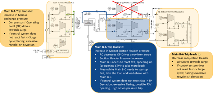
Figure 6 - Main B compressor A trip impact
- Poor performance control causes unnecessary flaring.
At present, the contractual IUGA (Associated Gas Utilization Index) can be as high as 97 to 98.5 percent, and the volumes of natural gas flared each month cannot exceed the limit set forth in the contractual IUGA foreseen for the same month in the approved annual production plan (PAP), plus 15 percent.
Excessive flaring will result in significant fines. For example, in cases where flaring exceeds the designated limit for 72h, production must be reduced to 50 percent capacity of the average of the last 30 days. For a 200,000 boe/day FPSO, a fiscal loss as high as $416,667 per hour at 50 percent production will occur, plus potential flaring penalties and fines.
Proper turbomachinery controls provide much smaller process variable excursions from the designated setpoint for significant process upsets, which results in less flaring potential.
In addition, flare control valves often have non-linear valve hysteresis, making flare control challenging. To reduce flaring and improve flare control quality, CCC flare control can utilize characterizers to handle this non-linearity, making flare control precise and reducing excessive flaring. - Tripping compression train due to a high or low process or driver threshold being exceeded.
If the primary loop’s process variable (usually common suction header pressure) becomes too low for whatever process reason, the train’s performance controller may be set-up, again with standard algorithms, to have the train’s antisurge valve(s) temporarily open – more than needed for surge control, to help restore the common suction header pressure back to the designated set-point as quickly as possible. This is a two-way modulation of the associated antisurge valve(s) in both the opening and closing directions.
The powerful limiting actions of the compressor’s performance controllers significantly reduce the potential of tripping any train due to a high or low process or driver threshold being exceeded. - Reduced operation performance and safety due to lacking proper parallel compression trains’ loadsharing and loadbalancing controls.
Often, OEM turbomachinery controls require base-loading one of the two parallel trains and applying suction pressure control to only one train. This can result in excessive recycle on the “swing” train. This can also result in hitting the gas turbine driver’s EGT limit on the “base loaded” train.
Alternatively, OEM controls may equalize the flowrates of the two parallel trains. This approach suffers from positive feedback and may be tuned only with very sluggish suction header pressure control. Whenever there is a process upset, operators often put the performance controllers in “manual” and manipulate train speeds manually. This is very risky.
Proper parallel compression train loadsharing and loadbalancing controls force parallel compressors to operate “equidistant – to – surge,” which results in applying necessary recycle only at the lowest possible throughput of the two trains. Both trains will tend to require recycle at the same time as shown in Figure 7. If recycle is necessary, it is possible to equalize the two trains’ recycle flow rates. Since both trains can collectively respond to surge inducing upsets, each train’s surge control margin may be configured as small as possible.
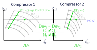
Figure 7 Compression parallel trains loadsharing and loadbalancing
- Hydrate formation can occur in the suction of a compressor.
Natural gas hydrates are ice-like crystalline solids formed from a mixture of water and natural gas subjected to high pressure and suitable low-temperature conditions. They are formed at low temperatures such as downstream of throttling a high pressure, saturated gas across an antisurge control valve. Hydrate formation at the suction side of a compressor (shown in Figure 8) may result in the following:
- Reduction in suction temperature
- Reduction in discharge pressure
- Reduction in compressor flow
- Low energy surge (the most dangerous event)
- Increase in discharge temperature
To avoid hydrate formation downstream of the antisurge valve, it is necessary to control the temperature of the recycle gas such that it stays above the temperature at which hydrates form. This is achieved by partially bypassing the after-cooler. For the main “A” and main “B” trains, maintaining a recycle gas temperature downstream of the antisurge valve above 30.0 degC is sufficient to avoid hydrate formation. - Reduction in suction temperature
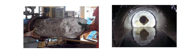
Figure 8 Hydrate formation in the suction of a compressor
- Valve stiction and/or failure to respond to a command signal may reduce the safety of compression trains. A proper turbomachinery controller shall be able to diagnose and prevent excessive valve stiction by partial stroke tests using the valves surrounding process parameters to detect and confirm correct valve response.
- Transmitter freeze and drift may lead compression trains to work under unsafe operating conditions. As FPSO operations rely on multiple transmitters to timely and accurately read operating conditions around compression trains for better control, the turbomachinery control system should be able to detect and alarm such transmitter freeze and drift.
- CO2 compression at high pressure is challenging because CO2 behaves far from ideal in its supercritical phase, posing a direct challenge to the operations of the CO2 compressor (and any injection compressors handling a significant CO2 content gas mixture in supercritical phase) and its associated piping and instrument design. Poorly designed compressors may result in compressor stage mismatch, unstable (and in some cases uncontrollable) compressor operation, recycle valve freezing and low compressor operation efficiency. Detailed and thorough analysis on the CO2 compressor, its associated piping and instrument shall be carried out during FEED stage to ensure safe, reliable and efficient compressor operation.
Need to know more about how to optimize your FPSO operation, resulting in higher FPSO uptime, increased throughput and reduced OPEX? Contact CCC today to speak with an expert and to get started.
References
[1] Adam Muspratt, Guide to FPSO (Floating Production Storage and Offloading), 2018
[2] Carranza Sánchez, Yamid & De Oliveira Junior, Silvio, “Assessment of the exergy performance of a floating, production, storage and offloading (FPSO) unit: Influence of three operational modes”, 2015