

Countless industries are racing to reach net zero carbon and methane emissions by 2050. In order to achieve this goal, companies are looking at ways to enhance asset energy efficiency while retaining positive net present value (NPV) on their carbon capture projects. Reducing capture technology costs in every stage -- design, installation, commissioning, and operation -- will be the key to hitting this sweet spot for many industrial enterprises. Where carbon capture is concerned, the optimization of a carbon dioxide (CO2) compressor through proper design and control can go a long way toward helping a company efficiently lower emission.
According to McKinsey, 57 percent of oil and gas emissions can be traced back to methane. Forty-three percent, meanwhile, are attributed to CO2. The act of capturing this carbon is not new to industries like oil and gas. For decades, CO2 has been captured from industrial process streams. But has been either released into the atmosphere or utilized for smaller-scale applications.
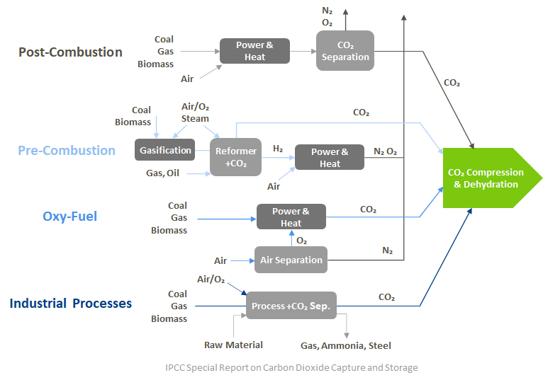
The capture process can take on multiple forms:
-
Post-combustion: CO2 is separated from the flue gas produced by the combustion of the primary fuel.
-
Pre-combustion: The primary fuel is processed through a gasifier with steam and oxygen. A shift reactor produces CO2 and hydrogen from the newly formed gas, and the CO2 and hydrogen are separated into independent streams.
-
Oxy-Fuel: Oxygen is separated from the air and used as an oxidant for fossil fuel combustion. The resulting gas is diluted with recycled flue gas, which creates final flue gasses consisting mainly of CO2 and water. This allows for a more concentrated CO2 stream that is more easily purified.
Carbon capture is also possible through LNG refrigeration trains. An acid gas removal unit captures carbon from natural gas feeds by utilizing chemical absorption, physical absorption, or a mixed solvents process. Integrated turbomachinery control has a critical role to play in reducing CO2 emissions by increasing operational efficiency, and by preventing trips in the Acid Gas Recovery Unit (AGRU) or LNG train.
Major Process & Operational Challenges of CO2 Compression
A number of challenges may be encountered when attempting to design and control a CO2 compressor for carbon capture use. Here are a few examples:
Non-Ideal Gas
Traditional compressor control designs are built around predictable gas behavior. When CO2 is compressed, the temperatures and pressures utilized cause it to behave as a non-ideal gas. CO2 is typically transported in its supercritical state. Beyond the critical point, there is no longer a boundary between the liquid and vapor phases and CO2 at pressures and temperatures higher than the critical point is a supercritical fluid. It is no longer in either a liquid phase or gas phase, but exhibits properties of both.
Stage Mismatch
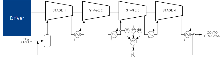
At a pressure ratio of 150, matching stages are a challenging target to reach for in-line four-section multi-stage compressors. Typically, an in-line CO2 compressor consists of an eight-stage LP compressor and a seven-stage HP compressor. Each compressor will have an intercooler as well as a cooler between the two compressors resulting in four compression sections.
Both surge and choke must be considered due to the way these compressors are designed. In the fourth section in particular, studies from CCC have shown that variable speed compressors running at moderate to low speeds may experience limited flow due to choke. This makes a surge event far more likely to occur in the first section. When speed is increased, there’s also a greater likelihood of surge occurring in section four.


Stage mismatch is less of an issue with integrally geared compressors as pinion speeds for each set of paired stages can be optimized as well as the ability to have cooling between individual stages. Integrally geared CO2 compressors are typically driven by a fixed speed motor and utilize inlet guide vanes to maintain the desired throughput.

Intercooling
When the pressure of a gas increases, its temperature is also increased. This effectively puts a limit on how much pressure each section can apply. For pressure to be safely increased from section to section or stage to stage, cooling of the gas must take place in between each.
However, fouling of an intercooler can complicate this process by causing the temperature of one of the sections to increase unexpectedly — typically in a way that cannot be reported by the control system. This has the potential to not only alter the downstream sections’ surge line but that of the entire compressor.
Flow Measurement
Calculating flow through a compressor typically necessitates the use of an orifice plate or FMD. As noted in our white paper, “Holding Back the Surge,” the flow is determined by measuring “the differential between the pressures across this FMD.” This information is then fed to the control algorithm.
That white paper also states that, “because of the great variation in the compressibilities, calculation of equivalent differential pressure signals is not practical.” For this reason, it is a best practice to outfit every antisurge controller with its own FMD — either in the suction or discharge of the stage — in order to ensure surge protection.
Multiphase Flow
Because of CO2’s behavior as a non-ideal gas when subject to increased pressures and temperatures, issues can occur in machines with only a single recycle valve. One example is the potential for the antisurge valve to freeze internally or externally due to very high discharge pressure.
Having individual recycling and antisurge control around each section limits the need for excessive venting for sections upstream of the 4th section and reduces the need for recycling to upstream sections at higher speeds. The potential for condensing through the recycle valves as well as the freezing of the valves are avoided. In addition, antisurge control is not affected if any of the intercoolers experience fouling.
CO2 Compression: Integrated Turbomachinery Best Practices
Engineering Design
In order to mitigate the various challenges of CO2 compression, the use of an integrated control system is recommended. Engineering design for this system should be part of the pre-FEED and FEED stages in order to:
-
Reduce risk
-
Stay on top of costs
-
Increase project design quality, control, and consistency

Antisurge Valve Sizing
For most projects, antisurge valve sizing will be necessary. This matches valve size to a compressor’s surge limit line at various operating speeds or guide vane angle, but does not take into account runup, rundown or an ESD event. It is generally recommended that antisurge valves have a capacity of two times the surge flow line.
Recycle Piping
For in-line compressors, having individual recycle and antisurge control around each compressor section limits the need for excessive venting for sections upstream of the 4th section and reduces the need of recycling to upstream sections at higher speeds. The potential for condensing through the recycle valves as well as the freezing of the valves are avoided. In addition, antisurge control is not affected if any of the intercoolers experience fouling.

For integrally geared compressors, there may be more than one set of guide vanes. Paired set of stages can have an overall recycle line and antisurge controller or an overall recycle line can be used across multiple sets of paired stages. The recycle piping and antisurge control may be defined by the number of stages with inlet guide vanes, any incoming sidestreams, as well as venting locations between stages.

Transmitter Location and Installation
Proper transmitter location and installation is key. Instrumentation should be located as close as possible to the compressor in order to get the quickest and most accurate information. Distance between the transmitter and the tap point should be minimized, with no horizontal runs in tubing and as few bends in the tubing as possible.
Using Integrated Capacity Control and Antisurge Control Together
This is recommended reading for those with CO2 compression trains that use a primary control variable, such as suction header pressure. Typically, when both capacity control and antisurge control are implemented simultaneously in such a setup, both manipulate the throughput of the compressor via two separate control loops. This can cause loop oscillation if left unchecked.
While many operators will place one or both of the control loops in manual to prevent this from occurring, the interaction between the two can be minimized by incorporating automatic feedforward control. This enables capacity control to coordinate with antisurge control so both work together to maintain a process variable or limit variable.
Parallel Load-Sharing Control
When compressor trains are operating in parallel, integrated control becomes necessary for proper load-sharing. There are other benefits to be derived from the integration of capacity and antisurge control, however. Automatic start and stop sequencing are consistently smooth, stable process control is maintained and the system operates within its constraints.

Parallel load-sharing offers a two-tier control response for the simultaneous operation of multiple compressor trains. The Loadsharing control system consists of a Master controller(s) (MPC) to maintain a header pressure(s), Loadsharing controllers (LSC) for each parallel compressor string/header along with the associated Antisurge controllers (ASC). The first tier response of load-sharing enables the regulation of section head pressure or another primary process variable. The second keeps compressors from recycling until all of their operating points reach their respective surge lines.
Trust CCC for CCS/CCUS Turbomachinery Optimization
If you have additional questions about carbon capture, utilization, and storage — and how CCC can optimize turbomachinery controls for these purposes — contact us today.